Serial Communication
The main characteristic of serial communication is the process of sending data one bit at a time, sequentially, through a communication channel or bus. Unlike parallel communication, where all bits of each symbol are sent together.
In order to enable the conversion, transmission and reception of data in a serial way, which were originally arranged in parallel, the UART format emerges, an acronym for Universal Asynchrounous Receiver/Transmiter.
The term “Universal” refers to the characteristic of the data format and speed being configurable, while “Asynchronous” refers to the way in which serial communication occurs, in which the devices are not continuously synchronized by a common clock signal.
Note
More details on UART communication can be seen in Introduction to UART Communication - microcontrollerslab.com.
In the case of Overo, we have three Communication Systems UART implemented by hardware at our disposal. What makes any manual implementation through software using GPIO unnecessary.
Now let’s understand how the UART communication protocol works. This communication works by connecting the transmitter (TX) of one device to the receiver (RX) of another device, in this case, only TX makes changes to the line voltage level , therefore, communication is, for each connection, a one-way street. Therefore, to perform a two-way communication we will use two connections, one will be the RX connection from device 1 with TX from device 2 and the other connection will be the opposite, RX from device 2 with TX from device 1, similar to the image below.

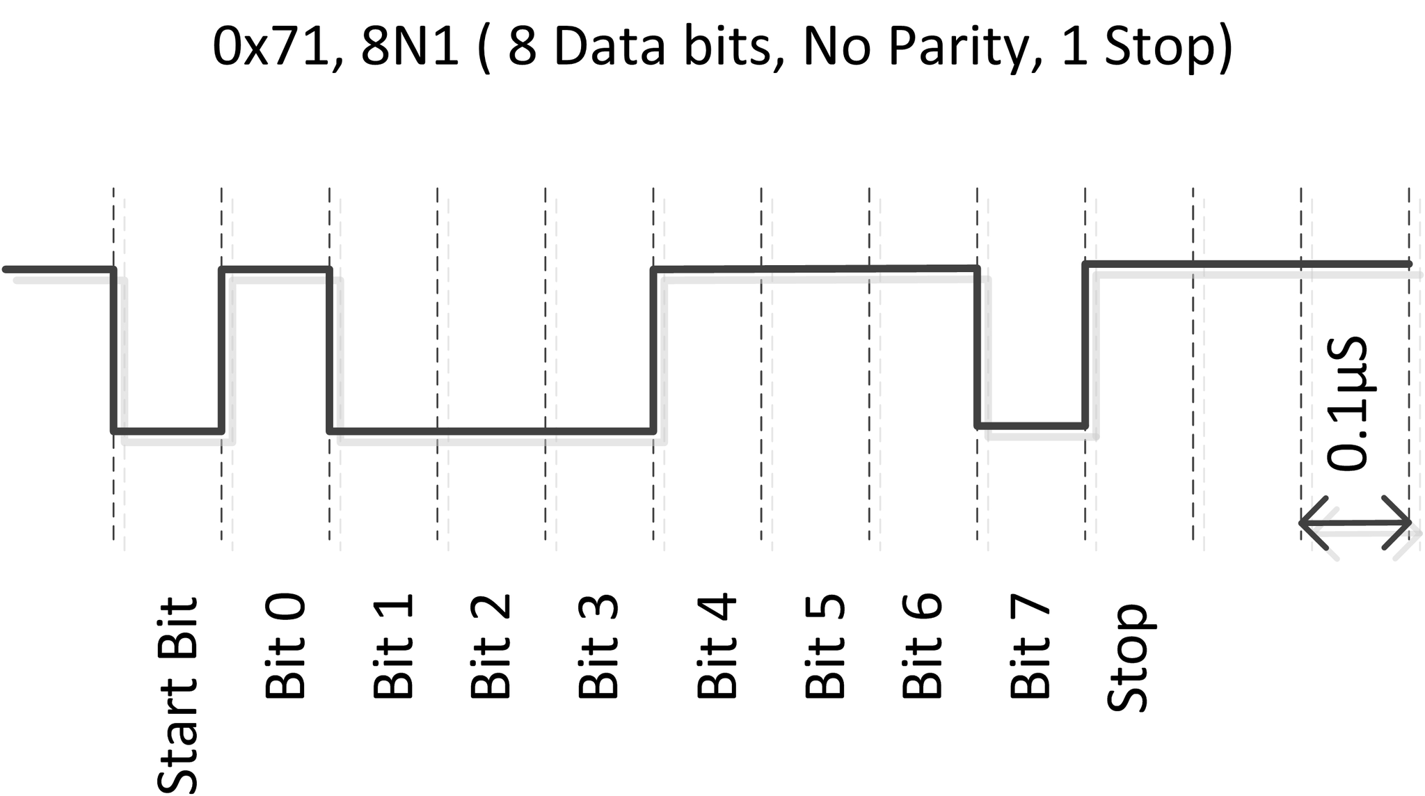
We can analyze the communication situation at bit level. For example, for a UART communication type “8N1” (8 data bits, 0 parity bits and 1 stop bit) we will have the channel in IDLE state, which means “not operating”, represented by the static voltage level high. Therefore, when the intention is to start the communication, a low level pulse is sent and then the eight data bits are sent, which will be accompanied by a stop bit in a high state.
It’s important to note that the function of the stop bit is to pause the transmission for some internal processing of the devices, therefore, there is no need for any additional time between the transmitted data.
As this is an asynchronous communication, it is essential that the speed of the communication is predetermined. This speed is usually given in Baud rate, a unit of measurement for the number of signal units sent per second.
Note
The term “Baud rate” is used to measure the speed of data transmission between devices. A baud is a measure of signaling speed and represents the number of changes in the transmission line (whether in frequency, amplitude, phase, etc.) or events per second.
The following figure shows a schematic illustrating how UART communication works. In the illustration, the communication speed is 10,000,000 baud/s.
Particularities of Gumstix Overo
By default, the Tobi expansion card provides only two of the UARTs available on Overo module computer for use via its pins. As can be seen in the image below, UART1 is connected to pins 10 and 9 and UART3 is connected to pins 22 and 21. It’s also important to say that the UART3 serial port is the same pin used by the USB console, ie , it’s the same pin that we use to control Gumstix from the computer, that is, in standard configuration system messages and messages to the system are sent through this port.
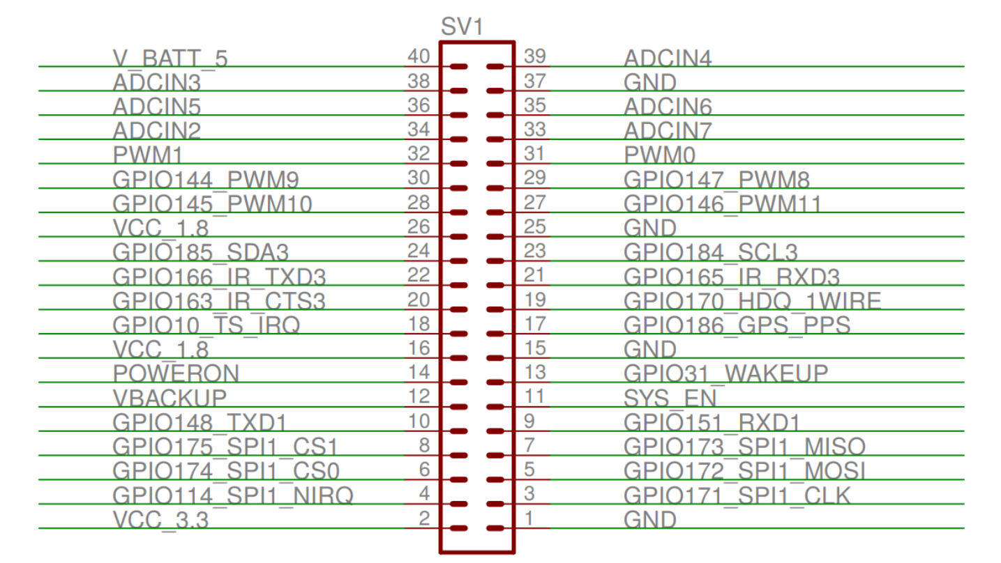
Pin diagram of the tobi expansion card.
If the two serial ports already mentioned are not enough, exist also the UART2 serial port. However, by default, it’s not available on any of the pins on the Tobi board for our use. In fact, it was reserved to communicate with Bluetooth, yet only later versions of the Overo embedded computer used by us have Bluetooth, so we can, if necessary, export UART2 to the pins and use them. To use this serial port, it is necessary to modify u-boot in order to multiplex its function to GPIO 146/147 which, as shown in the previous figure, are connected to pins 29 and 27. Therefore, to do this it is necessary to modify the file “overo.h” removing the command lines for the GPIO mode from pins 146 and 147, removing the lines that disable UART2 and adding the lines that enable serial communication over UART2.
To understand, in detail, what needs to be done and which registers will be changed, consult the serial communication section of the processor’s Technical Reference Manual (TRM). However, there is a topic in the Gumstix Discussion Forum that directly indicates what changes must be made to the ” u-boot” in order to use UART2, although the solution presented in that forum was not tested during this work.
UART configuration
As previously mentioned, the embedded computer has specific hardware for UART communication, in other words, it’s not necessary to perform a manual implementation to use UART communication, just write in some registers to send the message.
In fact, in our case it is even simpler because the installed operating system already has configured drivers for the application of serial communication. Therefore, it isn’t necessary to access the physical memory of the device, we just need to write in the driver what should be transmitted.
The serial communication drivers are files of type character, named “ttyOx”, where “x” represents the unique number of each UART. These drivers are located in “/dev” and function as a communication terminal.
For example, the “ttyO2” driver is the serial communication driver for the USB Console port, the same one we connect to the computer, that is, when writing to this port we will write on the computer connected to Gumstix and when reading this port we will be reading the computer. In other words, writing or reading in this driver will have the same final result of calling, respectively, the function printf () or scanf (), when a computer is connected to that port with the terminal open.
The configuration of the serial ports can be done in two ways, by command lines in the Linux terminal or by a code that changes the hardware settings. The simplest and, again, the most limited or least efficient is the configuration through command lines, the configuration in this way is usually used only when done by a human user in real time.
To perform the configuration through the Linux terminal, we must use the command stty, since this command has a huge number of parameters that allows to establish serial communication in the desired way.
Note
To view all parameters of the stty command, just run stty --help in the terminal.
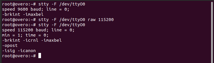
If, for example, the command line stty -F / dev / ttyO0 -a is executed, all the serial communication settings UART1 of the device will be printed. To print only the main settings, you must delete the -a, the last option of the command. If changing the speed is desirable, it can be changed simply by adding the desired speed to the end of the command line.
The figure below shows an example of configuring UART1 using the Linux command terminal.
The other way to configure the serial communication made by these drivers without manually changing the contents of the physical address of the memory is with the aid of the “termios.h” library. This library has a wide variety of functions that configure serial communication based on the parameters of a “termios” structure, also defined in this library.
Note
More information about the termios.h library can be found at termios.h - Linux manual page.
There are two parameters of UART communication, in addition to those mentioned above, which stand out, the minimum number of bits that are expected to be read at each reading attempt and the maximum time to wait for a new character after the transmission of the last character and after the minimum number of characters to be reached.
The minimum number of bits expected to be read and the maximum wait time for the next bit in tenths of a second can be configured with the following commands termios.c_cc [VMIN] = and termios.c_cc [VTIME] =, where termios is the name of its structure. For the speed setting, it is recommended to use the function cfsetspeed (), while the function cfmakeraw () configures, in addition to other parameters, the operation without parity bit and with 8 data bits. After making the adjustments to the structure, it is still necessary to execute the function cfsetattr () for the changes to be made in the UART.
Below is the code used to configure the serial communication of Overo computers. Note that in this configuration function the “O_NONBLOCK” flag was not used in the “open ()” function and the minimum number of characters to be returned after an attempt to read was set to 1, so if the code is executed and no information is entered sent to this channel the processor will wait forever for that character. The time count, set to 0.1 second, does not start until the minimum number of characters has been reached.
#include <stdio.h>
#include <string.h>
#include <unistd.h>
#include <fcntl.h>
#include <termios.h>

void main()
{
    struct termios cUART1;
    int UART1 = open("/dev/ttyO0", O_RDWR);

    if(tcgetattr(UART1,&cUART1))
        printf("Erro tcgetattr");
    cfmakeraw(&cUART1);
    cfsetspeed(&cUART1,B115200);
    cUART1.c_cflag &= ~CSTOPB;

    cUART1.c_cc[VMIN] = 1;
    cUART1.c_cc[VTIME] = 1;
    if (tcsetattr(UART1, TCSANOW, &cUART1))
        printf("Erro tcsetattr");

}
The following figure shows an example of UART1 configuration using the configuration code above.
Note
In order to simplify the configuration of the UART within another code, some modifications were made to the previous code to convert it into a function for configuring serial communication, as shown below:
int configUART1()
{
    struct termios cUART1;
    int UART1 = open("/dev/ttyO0", O_RDWR);

    if(tcgetattr(UART1,&cUART1))
        printf("Erro tcgetattr");
    cfmakeraw(&cUART1);
    cfsetspeed(&cUART1,B115200);
    cUART1.c_cflag &= ~CSTOPB;

    cUART1.c_cc[VMIN] = 1;
    cUART1.c_cc[VTIME] = 1;
    if (tcsetattr(UART1, TCSANOW, &cUART1))
        printf("Erro tcsetattr");

    return UART1;
}
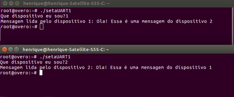
Once the configuration was made, the following code was also implemented in order to test the communication between two computers. In the test, one device sends a message to the other device that responds with a similar message to the first device, then both devices print the received message.
int main()
{

    int UART1 = configUART1();  // call the UART configuration function
    char dis[2], out[100], string[100];

    printf("What device am I?");
    scanf("%c", &dis[0]);
    dis[1] = 0;
    string[0] = 0;
    strcat(string, "Hello! This is a message from the device");
    strcat(string, dis);

    // testa UART
    write(UART1, string, strlen(string));
    sleep(1);
    read(UART1, out, 100);
    printf("Message read by the device %s: %s\n", dis, out);
    close(UART1);
    return 0;
}
Since the two devices are identical, it will be necessary to connect pin 10 of one device with pin 9 of the other device and vice versa. Using this code as a basis it is possible to send any message of up to 100 characters from one device to the other.
The following figure shows the result of testing the codes presented. In this figure we can see two Linux terminals, each linked to an embedded computer, and both call the same function, right after that we see the message read by each of the devices.
References
- PITA, H. C. Desenvolvimento de sistema de comunicação multiplataforma para veículos aéreos de asa fixa. Faculdade de Tecnologia, Universidade de Brasília, 2018.
- Universal asynchronous receiver-transmitter - wikipedia.org
- Asynchronous serial communication - wikipedia.org
- Como funcionam as UARTs - newtoncbraga.com.br
- UART Basics - ece353.engr.wisc.edu
- termios.h(0p) - Linux manual page - man7.org
- cfsetspeed(3) - Linux man page - linux.die.net